


The Freetronics LeoStick is a handy break-out board for the ATmega32U4 microcontroller. The board has a convenient USB stick format, and is based on the pinout and connections of the Arduino Leonardo reference design for compatibility with the Arduino IDE. Before you plug in your LeoStick for the first time please read this section of the forum for any updates on installation and use.
The LeoStick uses the ATmega32u4 microcontroller and works with most Arduino software, and is even electrically (but not physically) compatible with typical expansion shields. It provides the same expansion headers as the Leonardo and other models such as the Arduino Uno, but in a different physical layout to match the super-small board.
The LeoStick is powered automatically by the USB connection from a host computer, or you can connect an external 5Vdc regulated power supply to run it independently.

- Keep it in your pocket! Plugs straight into any USB port.
- On-board RGB LEDs, one for full programmable RGB use and the other for Power, USB RX and TX status.
- On-board piezo sound generator.
- Supplied with low profile header socket strips to easily plug in any modules or extra hardware.
- ATmega32U4 microcontroller with 32K of Flash, 1K of EEPROM and 2.5K of RAM, running at 16MHz.
- Regular AVR 6 pin ISP connector for reflashing the bootloader or direct application programming.
- On-board reset button.
- 0.1" pitch pin spacing, fits into solderless breadboard or veroboard pads.
Using the LeoStick with the Arduino IDE
The LeoStick can be programmed using the Arduino IDE, which is the software development environment designed to work with Arduino-compatible boards. Before you can load your programs onto the LeoStick you need to install the Arduino IDE (version 1.0.1 or newer, we recommend 1.0.4 or newer) and configure it to recognise your LeoStick board.
1. Download And Install Arduino IDE
If you don't already have the Arduino IDE (v1.0.1 or newer) installed, please download the latest Arduino IDE for your operating system from www.arduino.cc/en/Main/Software and install it. You'll also find more step-by-step guides for installation at www.arduino.cc/en/Guide/HomePage.
2. Download And Extract Board Profile
The "board profile" is what tells the Arduino IDE how to recognise a specific model of Arduino-compatible board. Download the latest board profile here. The current board profile version is 3.3.
The board profile is downloaded as a ".zip" archive. You should be able to double-click it to view and then extract the contents on your computer. Inside you'll find a directory named "LeoStickBoardProfile-master".
Note: If you have any previous LeoStick board profiles installed then you'll need to delete them before you install this new profile.
3. Install Board Profile
Check the location the Arduino IDE uses to store sketches, called the "Sketchbook" directory. On Windows this directory is called "Arduino" inside "My Documents". On OS X it is also called "Arduino", inside the "Documents" folder in your home folder. If you're not sure where the Sketchbook directory is on your computer, you can find it by launching the Arduino IDE, choosing Preferences from the File menu, and looking at the "Sketchbook Location" field.
Inside the sketchbook directory, create a new directory called "hardware" if it doesn't already exist.
Move or copy the board profile directory from Step 4 into the "hardware" directory. You should end up with a structure like "sketchbook/hardware/LeoStick". There should be a file in that directory "sketchbook/hardware/LeoStickBoardProfile-master/boards.txt" (plus some other subdirectories.)
Restart the Arduino IDE so that it will recognise the new profile. Under the Tools -> Board menu you should see the additional options for LeoStick. On Arduino v1.0.x, these options are Freetronics LeoStick v1.0 and Freetronics LeoStick v2.0.
On Arduino v1.6 or newer, there is only a single Freetronics LeoStick entry. (LeoStick bootloader V1.0 is not supported on Arduino 1.6, only bootloader V2.0. See below for details.)
4. Install USB .inf File (Windows Only)
For Windows users only, the USB device file for the LeoStick must be downloaded and used for first-time installation of the LeoStick's USB port. See http://www.freetronics.com/pages/installing-the-usb-driver-file-for-windows. Linux and MacOS do not require this step.
5. Check LeoStick Bootloader Type
You need to select the correct LeoStick Board (V1.0 or V2.0) in the Arduino IDE in order to upload sketches. If you choose the wrong version the upload process will not work correctly .
All recent LeoSticks are V2.0 and have the "Caterina" bootloader installed just like the final Arduino Leonardo. If your LeoStick is brand new, it will be V2.0 - you can skip to the next step.
Early LeoSticks are V1.0 and have the "Diskloader" bootloader installed (based on the Arduino Leonardo beta.) V1.0 has some limitations, and only supports Arduino IDE V1.0.x, not 1.6 or newer.
The easiest way to identify your bootloader is to press the "Reset" button on your LeoStick (which starts the bootloader.) The LED will pulse on and off as if it is "breathing" for several seconds, and the two bootloaders breathe at different rates.
The V2.0 "Caterina" bootloader breathes fast (more than once a second):

The V1.0 "Diskloader" bootloader breathes much slower (about once a second):

It is possible to upgrade a LeoStick V1.0 to the V2.0 bootloader.
6. Initial Port Setup
Now we're ready to do the initial board and port setup. You won't need to do this again unless the serial port identifier changes such as when using a different USB port on your computer.
Launch the Arduino IDE, and select Tools > Board > Freetronics LeoStick v2.0 (or v1.0)
Before connecting your LeoStick to the USB port, have a look at the list of ports in Tools > Serial Port. That's where your LeoStick is going to appear when you plug it in. Note: this menu option may be disabled until a new serial port appears, so if that's the case simply proceed to the next step.
Connect your LeoStick to the computer USB port. After a short while if you look at Tools > Serial Port again you'll see a new port appear: that's the LeoStick ready to be used. Select that port now with Tools > Serial Port so there is a tick mark next to it.
Compiling and Uploading Your First Sketch
Choose File > Examples > Digital > Blink. You'll see the code for Blink open in the IDE.
Select Sketch > Verify/Compile, you've now built (compiled) the program ready to be loaded.
Lastly, to load the program into the LeoStick, select File > Upload to I/O Board. You'll see the combined PWR/TX/RX LED flicker different colours while the upload is being done.
A few seconds later the RX and TX indicators will go off, the board will reset, and the red D13 LED will begin flashing on and off at 1 second intervals. Congratulations! You've now compiled and uploaded your first sketch to the LeoStick. Try experimenting with changing the delay values in the sketch and repeating the process to see the LED blink at different rates.
If you are having problems getting the sketch to upload, try pressing the reset button immediately after you press Upload in the Arduino IDE. This may be particularly noticeable if you are using Windows and updating from a previous version of the board profile, but it should only happen for the first upload with the new profile.
Problems Uploading on Linux
If you're having problems uploading on a recent Linux distribution with Modem Manager (recent default Ubuntu, Fedora & Debian installs all have this.) then you may need to tell Modem Manager to ignore the LeoStick bootloader instead of probing it.And then restart udev by running a command like sudo /etc/init.d/udev restart.ATTRS{idVendor}=="26ba", ENV{ID_MM_DEVICE_IGNORE}="1"
ATTRS{idVendor}=="20a0", ENV{ID_MM_DEVICE_IGNORE}="1"
Using the RGB LED
Most Arduino models include a red LED already connected to digital I/O pin D13, so that you can easily control it from software without needing to add any other parts. The LeoStick instead includes a full RGB LED, with the red element connected to D13. It's therefore compatible out of the box with example sketches that assume there is a red LED connected to D13, but gives you the flexibility of being able to display a full range of colours by blending the red, green, and blue elements. The green element is connected to D9, and the blue element to D10. The pin assignments are printed on the bottom of the LeoStick for easy reference.
Using Piezo Sound Output
The piezoelectric transducer mounted on the bottom of the LeoStick is connected to digital I/O pin D11, which you can use to generate different tones.
Warning: On a LeoStick V1, do not use the "tone()" function with the Piezo speaker! V1 is based on the Leonardo beta firmware, where tone() was non-functional. The timer used for pulse-width modulation on D11 causes the board to lock up, and the only way to recover is to upload a new sketch during the first few seconds or so after resetting the board when the bootloader is active. You can update the V1 bootloader to V2 to get around this problem, or generate tones on a V1 by using variable delays in a loop.
LeoStick Discussion Forum
There is a special section of the Freetronics Forum for discussion of the LeoStick:
Freetronics LeoStick Forum Section
Resources
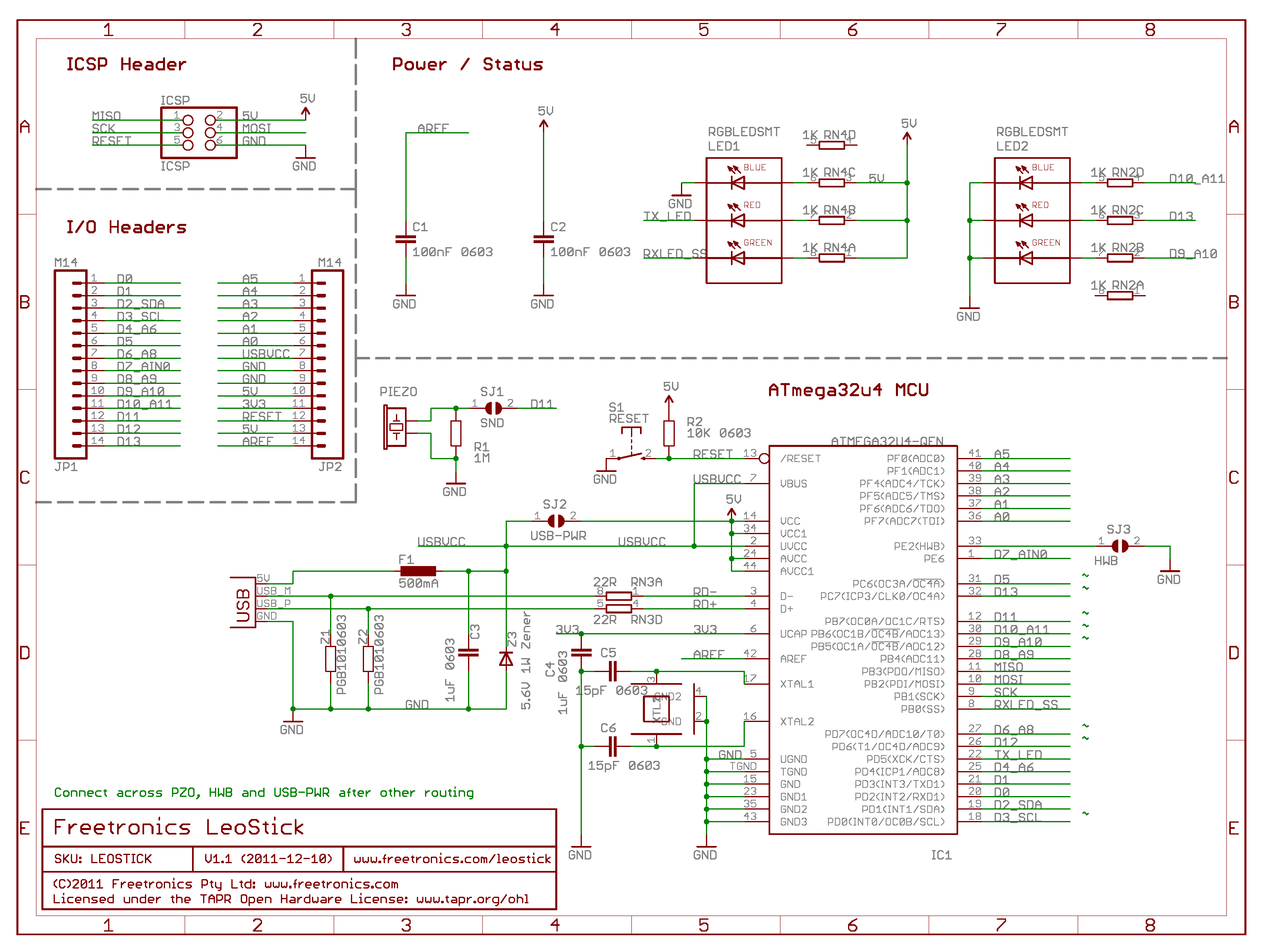
Schematic

LeoStick Specifications
| Microcontroller | ||
| MCU Type | Atmel ATmega32u4 | |
| Operating Voltage | 5V | |
| MCU Clock Speed | 16 MHz | |
| LeoStick | ||
| Input Voltage | 5V DC via USB port or "5V" header | |
| Digital I/O pins | 14 (6 provide PWM output) | |
| PWM Output Pins | 3, 5, 6, 9, 10 and 11 (V2.0), 3, 5, 9, 10 and 11 (earlier models, V1.0) | |
| Analog Input Pins | 6 (analog input pins also support digital I/O, giving 20 digital I/O total if required) |
|
| Analog Resolution | 10 bits, 0-1023 at 5V AREF is approx 0.00488V; 4.88mV per step | |
| Current Per I/O Pin | 40 mA maximum | |
| Total Current For All I/O Pins | 200mA maximum | |
| Current For 3.3V Output | 50mA maximum | |
| Memory | ||
| Flash Memory | 32 KB Flash Memory, of which approximately 2 KB is used by the bootloader | |
| SRAM, EEPROM | 2.5 KB SRAM, 1 KB EEPROM | |
| Communications | ||
| Serial |
1 x hardware USART (RX=D0, TX=D1) |
|
| SPI (Serial Peripheral Interface) |
On six-pin ICSP header (MISO=1, SCK=3, MOSI=4, see schematic for layout.) |
|
| I2C (aka TWI, Two Wire Interface) |
I2C aka TWI (Two Wire Interface) (SDA=D2, SCL=D3.) |
|
| Other | Integrated USB programming and communication port. Many other one-wire, multi-wire, LCD and expansion devices supported by free code and libraries | |


