


Note: the RFID Lock Shield kit is based on the "RFID Access Control System" project in the book "Practical Arduino". For a detailed discussion of the operation of the circuit please see the book.
The RFID Lock Shield has been designed for easy assembly and you may find you can assemble it simply by following the overlay printed on the PCB. Even if you have no previous experience with electronics you should be able to get through it by following this guide.
Note that this guide does not attempt to teach you how to solder: if you've never soldered before, we suggest you consult one of the excellent online tutorials such as http://store.curiousinventor.com/guides/How_to_Solder
Step 1: Check / Identify Required Parts
You'll find that some of the parts in the RFID Lock Shield kit look very similar but they are actually quite different, and it's important that you insert the parts in the correct locations. Start by spreading them out on a tray or clear bench area so you can see them clearly.

| Qty | Part |
| 1 | 470R resistor |
| 1 | 680R resistor |
| 3 | 2K2 resistor |
| 1 | 4K7 resistor |
| 2 | 1N4001 power diode |
| 2 | 100nF ceramic capacitor |
| 1 | 47uF 25V electrolytic capacitor |
| 2 | Red 3mm LED |
| 2 | Green 3mm LED |
| 1 | Blue 3mm LED |
| 1 | 2N2222 NPN transistor (TO-92 package) |
| 1 | 7809 9V voltage regulator (TO-220 package) |
| 1 | Tactile button |
| 1 | 12V SPST relay |
| 1 | 3-way PCB-mount right-angle male header |
| 1 | 4-way PCB-mount right-angle male header |
| 1 | 3-way line-mount female header |
| 1 | 4-way line-mount female header |
| 2 | 2-way PCB-mount screw terminal |
| 2 | 1x6 male break-away header |
| 2 | 1x8 male break-away header |
| 1 | RFID Lock Shield PCB |
Note: The kit does not include an RFID module. This shield is designed to work with a wide range of modules so please select one that is suitable for the RFID tags you wish to read. RFID reader modules known to work with this shield include:
- ID12
- ID20
- RDM630
- RDM880
- HF Multitag
Step 2: Voltage Regulator
Fitting the 9V voltage regulator is a little tricky, so it's best to do it at the start before other parts get in the way. Start by using a pair of pliers to bend the leads to a 90 degree angle as shown in the photo.

The leads have to pass down through the PCB while the regulator lies flat on the board.
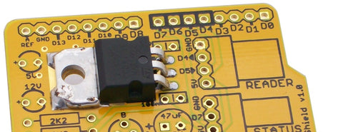
Solder the leads under the PCB and trim them off. Now for the tricky bit: soldering the regulator heatsink to the PCB. Directly under the regulator body is a bare metal surface on the PCB, and by thermally connecting the regulator to the PCB we can use the PCB itself to help dissipate heat generated by the regulator. One way to do that is to use a small nut and bolt through the hole to clamp the regulator to the PCB, but we'll solder it instead.
The corners of the heatsink have small chamfers cut off them, exposing a small part of the PCB surface underneath. Push your soldering iron into the chamfer to heat up both the heatsink and the PCB surface at the same time so that you can get solder to bond to them both and join them together. Because the heatsink and the exposed PCB surface have a lot more thermal mass than a typical component lead you'll need to apply a good amount of heat before solder will melt and adhere to them.
Step 3: Resistors and Diodes
A good general principle is to fit the lowest parts first and work up, so next fit the resistors and power diodes. Note that two of the supplied resistors don't mount on the PCB: the 470R and 680R resistors are provided for you to build a remote status display, and aren't required for the shield. Only the 2K2 and 4K7 resistors go on the shield.
Resistors are not polarised so it doesn't matter which way you fit them to the board. However, it's customary to align the colour codes so that they all read in the same direction and look neat.
Note, however, that the diodes are polarised and it's critical that you insert them the correct way around. If you look closely at the diode body you'll see that one end is marked with a stripe. The PCB overlay also has the stripe marked, so if you match up the markings you should be fine. As you can see in the photo below, the diodes have their stripes towards each other.

Bend the leads of the resistors and diodes 90 degrees near the end of the body and insert them through the PCB as shown. Spread the legs out 45 degrees underneath the PCB to hold the parts firmly in place, then turn the PCB over and solder each joint. Clip off the excess leads.
Step 4: Connectors, Ceramic Capacitors, and Reset Button
The 3-way and 4-way right-angle headers need to be soldered in place as shown. It may be easiest to hold them in place with some tape or blue-tac while soldering so that you don't burn your fingers and they stay straight against the PCB.
The pair of 100nF ceramic capacitors (marked "104" on the body) are fitted near the voltage regulator.
When that's done, clip the tactile button into place and solder it under the PCB. The leads are spaced so that it can only be clipped into place with the correct orientation, so don't force it by bending them out of shape. If you have to do that, it's possible you have it oriented the wrong way around.

Step 5: LEDs, Transistor, and Electrolytic Capacitor

If you look closely at the PCB you'll see that each LED has a tiny "+" symbol next to the positive lead. To keep it simple we deliberately oriented all the LEDs around the same way, with the positive lead to the left and the negative to the right when viewing the PCB as shown in the photo.
Next fit the 2N2222 transistor as shown. Orientation is important, so make sure it has the flat side towards you. You'll probably have to bend the middle lead out slightly to make it fit into the holes on the PCB, and you don't need to push it right down flush. Doing so would put mechanical strain on the leads so TO-92 packages are typically mounted so that they float a few millimeters above the surface of the PCB.
The big 47uF electrolytic capacitor is fitted near the center of the PCB, and it's polarised so watch the orientation. The body of the electrolytic is marked to show the position of the negative ("-") lead, and the PCB is marked with a "+" to show the position of the positive lead. Once again we kept it simple by aligning the positive lead on the left and the negative on the right, just like the LEDs.

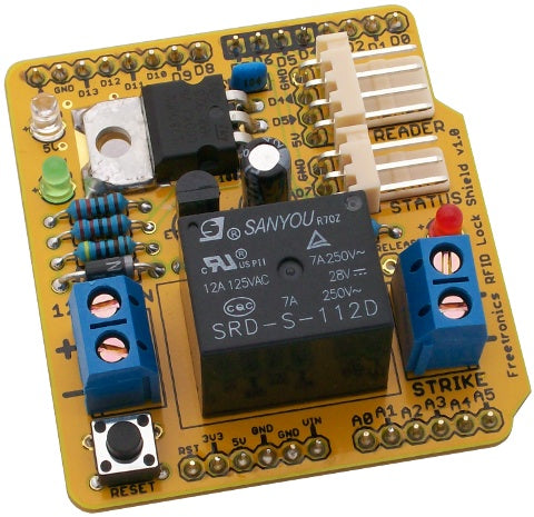
Step 6: Screw Terminals, Relay, and Arduino Headers
The screw terminals are easy: just pop them in so that the cable entrances are towards the edge of the PCB, and solder them in place.
The relay itself is also a simple part to fit, and it can only be inserted into the PCB one way around.
Because the RFID Lock Shield has a large relay sticking up quite high, it's not possible to use it with stacking headers to mount another shield on top. It has been supplied with regular break-away headers, and the easiest way to fit them and have them correctly aligned is to first insert the headers into your Arduino and then sit the shield on top. You can then solder the top of each header to the shield PCB, and when you remove it from the Arduino they will all be neatly aligned.
Step 7: RFID Reader Module
Because this shield is designed to work with a wide range of RFID modules, you'll need to make the connections as appropriate for your specific module. The shield uses serial communications to obtain readings from the module so the 4-way header provides GND, 5V, RX (D4) and TX (D5) connections.
When connecting serial data lines it's easy to get confused about what TX and RX actually mean. For example, some devices are marked so that "TX" means the connection from which the devices sends data, ie: data out from the perspective of the device. Other devices are marked so that "TX" means the connection that goes to the "TX" pin at the other end of the connection, ie: data in from the perspective of the device.
We've put small "in" and "out" arrows on the PCB to show the direction of data flow and (hopefully!) remove the ambiguity. In this context we're looking at it from the perspective of the shield, so pin D4 is used to receive data from the RFID module and should therefore be connected to the "TX" pin of the module itself.
Step 8: Status Indicator LEDs
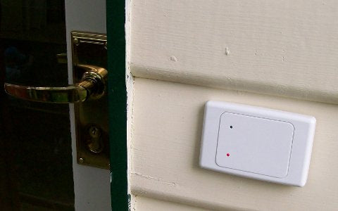
We've included spare red and green LEDs and matching current-limiting resistors along with a line-mount 3-way connector so that if you wish to assemble a remote status display you can do so by following the directions in Practical Arduino. How you construct your status display is up to you, and will depend on the physical installation of your RFID reader.
The photograph shows red and green status LEDs mounted in a blank electrical wall plate, with the RFID reader hidden behind the center of the plate.
Step 9: Connect Strike Plate
Use heavy-gauge hookup wire such as figure-8 speaker cable to connect your electric strike plate to the pair of screw terminals marked "STRIKE" on the shield. Mounting the strike plate is dependent on your specific requirements.
Step 10: Connect 12Vdc Power Supply
Connect a 12Vdc power supply such as a plug-pack (wall-wart) to the screw terminals marked "12Vdc IN", taking care to match the positive lead to the "+" terminal and the negative lead to the "-" terminal. The shield includes a diode to protect it against reverse polarity so if you get it wrong there shouldn't be any damage to your shield or Arduino.
Note that the power supply needs to be able to supply sufficient current to drive the strike plate without dropping its output voltage significantly. A power supply capable of supplying 12Vdc with no load may drop its output voltage significantly as soon as a strike plate starts pulling current from it, causing the voltage regulator on the shield to drop out and the Arduino to reset. If you discover that your Arduino resets every time the strike plate fires you may need to use a power supply with a higher current capacity.
Step 11: Load Sketch
The project description in Practical Arduino includes an example sketch that stores authorised RFID tag IDs internally and then activates the strike plate when a tag with a matching ID is read. You can download the sketch source code from:


