


When connecting an Arduino to an Ethernet network it can be really annoying that you need to run two cables to it: one for the LAN, one for power. It's particularly annoying if you're going to be putting the Arduino in some strange location with no easy access to power. Wouldn't it be nice if the Arduino could just draw power from the network connection?
The solution is called "Power-over-Ethernet" (commonly referred to as "PoE"), which puts a DC voltage onto specific pairs of the Ethernet cable so that devices connected to the network can use it as a power source.
General Concepts
PoE involves several different elements and can be configured in a variety of ways. In general though there are two important parts: the power sourcing equipment,or PSE, and the powered device, or PD.
The power sourcing equipment is located at the "switch" end of each network segment and supplies power to that segment. There are two ways the PSE can be set up: as a "powered switch", or as a "midspan injector". A powered switch is located at the end of the segment, such as a commercial switch with built-in PoE support. With a powered switch any cables you plug into the switch are automatically provided with power. The alternative is a midspan injector, which is a device that sits between the switch and the network segment and allows you to add PoE support to a regular non-PoE switch.
The powered device is connected to the powered network segment and draws power from it: in our case that'll be an Arduino.
A typical PoE system that consists of a regular Ethernet switch, a midspan injector, and a powered device looks something like this:

As far as the data connection between the switch and the PD is concerned, the midspan injector is totally transparent. Data passes directly through it unhindered. However, some of the wires inside the "powered" side LAN cable have power applied to them by the midspan injector which the PD can then use if it is configured to do so.
Power-over-Ethernet Standards
Early PoE systems were created by various companies with no particular standard in mind, so unfortunately there are a number of systems around that are not compatible with each other. Different companies used different voltages, different polarities, and different pin assignments - sometimes even varying between products manufactured by the same company!
Thankfully a standard has now been defined and modern PoE systems have converged to the point that they are mostly compatible. You can read about the standard, designated "802.3af" (2003) and the newer "802.3at" (2009), on Wikipedia. But even with the 802.3 standard it's not all clear sailing, because the standard itself is quite painful to implement. It stipulates the use of up to 48V (more than typical components such as voltage regulators can handle) and a signalling scheme to allow the PD to tell the injector how much power it will require. Implementing a full 802.3 standards-compliant powered device is therefore far more complex than it really should be.
Many hobbyists therefore implement a simplified system that uses the same connections as the 802.3 standard, but runs at a lower voltage and doesn't use a signalling scheme.
The most common PoE pin assignment typically used with 10/100base-T Ethernet (which only uses 2 of the 4 pairs in the cable for data) is as follows:

| Pin | Use | Description |
| 1 | RX+ | Receive data + |
| 2 | RX- | Receive data - |
| 3 | TX+ | Transmit data + |
| 4 | DC+ | Power-over-Ethernet + |
| 5 | DC+ | Power-over-Ethernet + |
| 6 | TX- | Transmit data - |
| 7 | DC- | Power-over-Ethernet - |
| 8 | DC- | Power-over-Ethernet - |
Gigabit Ethernet uses all four pairs instead of just two, so instead of having the DC power delivered on spare pairs it's delivered on the data wires using inductive coupling. There are no Gigabit-capable Ethernet shields for Arduino though.
Setting Up A Midspan Injector
The most low-tech (and cheapest) way to inject power into an Ethernet segment is to modify an Ethernet cable. We'll demonstrate using a typical patch lead but you could just as easily do the same thing to permanently-installed Ethernet cable. Start by carefully stripping away the outer insulation near the end of your cable that will be connected to your switch, exposing around 50mm (2") of the inner cable pairs as shown.
Next you need to determine which pairs you should cut. Unfortunately there are a number of colour-coding standards for Ethernet cable so if you can't see the colours through the RJ45 jack and match them up to the correct pin numbers, the only real way to determine this is to test the cable. One trick is to use a multimeter in resistance-testing or continuity-testing mode with one probe touching a known pin on one of the RJ45 connectors, and then use a dress-makers pin to pierce the insulation of the conductor and touching it with the other multimeter probe. That way you can determine which colours correspond to pins 4, 5, 7, and 8 as shown in the pinout diagram above.
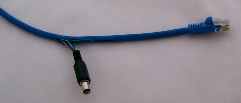
Once you know which colours correspond to those pins, cut the appropriate conductors near the end of the stripped-back section that's closest to the RJ45 connector. This will leave you with close to 50mm of cable that you can separate out of the bundle as shown below.

Strip back about 5mm of insulation from the end of each cable, then twist the pair of positive wires together and the pair of negative wires together. Then use a soldering iron to "tin" each pair so they are ready to connect to a power jack.
Solder each pair to the appropriate pins on a power jack. It's probably most convenient to use a 2.1mm DC jack since that's the same as the power connector on the Arduino, and you'll be able to plug in the same power pack as you would use with the Arduino directly. Don't forget to pre-fit the jack sleeve over the wire, because you can't get it on later once you've soldered it on!

Screw the jack sleeve onto the back of the DC jack and you're ready to go. Plug the cable back into your switch and connect a device at the other end to make sure the LAN connection still works after your modifications.
If you connect a power supply to that power jack you will now have power available on that network segment.
Modifying an Ethernet cable is a good way to go if you want to keep everything as cheap as possible, but a neater solution is to use a midspan injector. This will allow you to connect everything up without doing any soldering, doesn't require modifying the cable, adds some power-supply smoothing, and allows you to use a single power pack with multiple network segments.
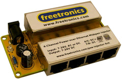 For cheap PoE with an Arduino it's not necessary to use a midspan injector that supports the full 802.3 standard. A simple injector that performs the same job as the hand-spliced cable described above is all you need. Freetronics have a simple 4-channel PoE Midspan Injector (Single Sided) that works just fine with an Arduino: simply connect the "switch" side to your Ethernet switch with short patch cables, plug your regular LAN cables into the "device" side, and connect an appropriate power supply to the 2.1mm DC power jack. The 4-channel injector includes a smoothing capacitor to help remove any voltage variation in the power supply and a "bridge rectifier" that takes either DC input polarity (or even AC input) and converts it to place DC+ on pins 4/5 and DC- on pins 7/8.
This particular midspan injector does not attempt to do any voltage regulation, so whatever voltage you put into it is the voltage that will be sent down the wire to your powered devices. Make sure you use a power supply that is appropriate for the devices you will connect, as described below.
Setting Up A Powered Device
If your Powered Device does not have built-in PoE support you will need to separate out the power from the Ethernet cable and connect it to the device's power socket. A common scenario is using an Arduino with an Ethernet shield that does not support PoE.
Just like when setting up the injector, there are two common ways to do this. The cheapest is to cut into the LAN cable and attach a DC plug that can then be plugged into the Arduino's DC power jack. Use the technique described above to strip back the cable, determine the correct conductors, separate them out, and solder on a 2.1mm DC plug. You can then plug the RJ45 connector into the Ethernet shield and the DC plug into the Arduino as shown below. The power injected into the network segment will never even reach the Ethernet shield so there's little danger of it being damaged.
A neater way to achieve the same end result without doing any cable cutting or soldering is to use a device called a "PoE splitter" that connects between the LAN cable and the device. It has a socket into which you can insert the LAN cable, and then connects to the RJ45 port on the Ethernet shield and the DC jack on the Arduino.

If you have a Powered Device with built-in PoE support then your job is really easy. For example, the Freetronics Ethernet Shield includes built-in PoE support and can extract the voltage supplied on the PoE pairs and send it through to your Arduino's on-board voltage regulator. With this approach you don't need anything additional at the PD end: just plug it into the powered network segment and you're ready to go. No mess, no fuss.
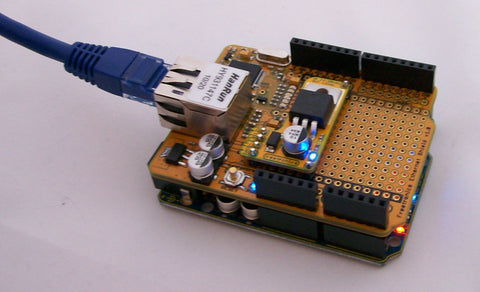
If your power sourcing equipment (such as a midspan injector) supplies a voltage that is safe for your Arduino to use directly, such as a DC voltage from about 7V to about 14V, you can simply put a pair of jumpers across the PoE header of the Ethernet shield so that the PoE "+" header connects to Arduino VIN, and the PoE "-" header connects to Arduino GND. The picture below shows an Ethernet shield fitted to a Freetronics TwentyTen and being supplied with approximately 9V via the Ethernet cable. The TwentyTen is powered up and running from the power supplied via the LAN:

If your power sourcing equipment supplies a higher voltage, such as 16V or 24V, it's not safe to simply pass it directly to the Arduino's voltage regulator using simple jumpers as shown above. In that situation you should fit a daughter-board to the Ethernet shield so that it pre-regulates the incoming power down to a safe level before passing it on to the Arduino. For input voltages between 14V and 24V, Freetronics has a PoE Voltage Regulator 14-24V available. The PoE Regulator uses a simple linear voltage regulator to trim the input voltage down to 12V before it is sent to the Arduino, saving the Arduino's voltage regulator from having to dissipate a larger voltage and protecting the Arduino's input capacitors (which have a relatively low voltage rating) from damage:
To connect your Powered Device to a network with Power Sourcing Equipment that supports the full 802.3 standard, things become a little more complicated. Standards-compliant PDs must accept up to 48V from the network and implement an active signalling mechanism to tell the PSE how much power they need, so implementing it isn't so simple. To make it easier for you we've created a daughter-board for the Freetronics Ethernet shield that will allow it to operate as a full 802.3-compliant PD, accepting up to 48V and identifying itself to the PSE as required by the standard: PoE Regulator 802.3af.
Feedback?
Got a comment or suggestion about this tutorial? Shoot us an email!


