


The Freetronics OLED128 is a 128x128 pixel full colour 1.5" OLED display module, with an Arduino-compatible interface. The FTOLED library enables graphics display on the OLED128.
This is the QuickStart guide for OLED128 on Arduino, there is also a guide for OLED128 on Raspberry Pi.


The OLED128 also features an onboard MicroSD card slot that can be used to store graphics or other data.
In this guide we’ll show how to connect the OLED128 to your board, and how to install the FTOLED library into the Arduino IDE.
Connecting the OLED128
IMPORTANT: If you're using either the OLED Shield or OLED Stick adapter board with your OLED128, you should follow the directions in the OLED Shield QuickStart guide or the OLED Stick QuickStart guide.
On the back of the OLED128 you’ll see there’s a 10 pin header, with numbers printed to indicate pins 1 & 2:

Start by wiring up the connections marked as "Required for OLED":

And then connecting them to an Arduino-compatible board:
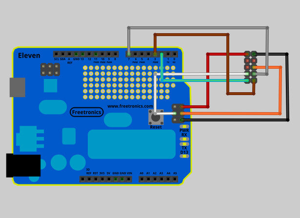
(Click the diagram to view full-size)
| OLED Pin | Signal | Connect To |
|---|---|---|
| 1 | 5V | ICSP 2 or 5V Pin |
| 2 | GND | ICSP 6 or GND Pin |
| 3 | ||
| 4 | ||
| 5 | ||
| 6 | MOSI | ICSP 4 |
| 7 | SCK | ICSP 3 |
| 8 | OLED CS | Digital Pin 7 (configurable) |
| 9 | OLED DNC | Digital Pin 2 (configurable) |
| 10 | OLED RST | Digital Pin 3 (configurable) |
Alternative Connections
The above example uses the 6-pin ICSP header to connect two SPI pins (MOSI, SCK) and also 5V and Ground. However some Arduino-compatible boards have the same SPI functionality on other pins.
Alternative wiring for Freetronics Eleven and other Uno-compatibles (Atmega328p or Atmega168p):
| OLED Pin | Signal | Connect To |
|---|---|---|
| 1 | 5V | 5V Pin |
| 2 | GND | GND Pin |
| 3 | ||
| 4 | ||
| 5 | ||
| 6 | MOSI | Digital Pin 11 |
| 7 | SCK | Digital Pin 13 |
| 8 | OLED CS | Digital Pin 7 (configurable) |
| 9 | OLED DNC | Digital Pin 2 (configurable) |
| 10 | OLED RST | Digital Pin 3 (configurable) |
Alternative wiring for Freetronics EtherMega or other Mega-compatible:
| OLED Pin | Signal | Connect To |
|---|---|---|
| 1 | 5V | 5V Pin |
| 2 | GND | GND Pin |
| 3 | ||
| 4 | ||
| 5 | ||
| 6 | MOSI | Digital Pin 51 |
| 7 | SCK | Digital Pin 52 |
| 8 | OLED CS | Digital Pin 7 (configurable) |
| 9 | OLED DNC | Digital Pin 2 (configurable) |
| 10 | OLED RST | Digital Pin 3 (configurable) |
On an Arduino Due, LeoStick, or other Leonardo-compatible board the only SPI pins are on the 6-pin ICSP header, so these are the ones you must connect in order to use the OLED128.
Note that digital pins 2,3 & 7 are used by default in the FTOLED examples. However these pins are configurable, you can use any non-SPI digital pins for these if you edit the sketch before uploading. This means on an Eleven or other Uno compatible you can use any pins but 11-13. On EtherMega & other Mega compatibles you can use any pins but 50-52. We recommend using 2,3 & 7 if you can.
What Cables To Use
You can wire the OLED128 up using a mix of female to female and male to male breadboard wires.

Or you could use a 10 pin 2x5 IDC cable and male to male breadboard wires, like this:

Or even solder a 2x5 pin header to a ProtoShield.
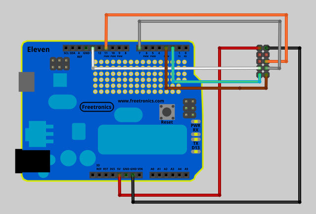
Connecting the MicroSD Card Slot
To use the MicroSD card slot as well as the OLED display, two additional wires need to be connected from pins 3 & 5 on the OLED connector:

| OLED Pin | Signal | Connect To |
|---|---|---|
| 1 | 5V | ICSP 2 or 5V Pin |
| 2 | GND | ICSP 6 or GND Pin |
| 3 | SD CS | Digital Pin 4 (configurable) |
| 4 | SD CD | Can leave unconnected |
| 5 | MISO | ICSP 1 |
| 6 | MOSI | ICSP 4 |
| 7 | SCK | ICSP 3 |
| 8 | OLED CS | Digital Pin 7 (configurable) |
| 9 | OLED DNC | Digital Pin 2 (configurable) |
| 10 | OLED RST | Digital Pin 3 (configurable) |
Note about cabling
SD cards can be quite selective about cable quality. Try to use good quality low impedance cable, avoid unnecessary junctions. We recommend keeping the overall cable length to no more than 15cm.(On the other hand, the OLED display itself is quite forgiving when it comes to cable quality - 75cm or longer is no problem to just display graphics.)
SD CD (Card Detect)
Pin 4 on the OLED128 connector (“Card Detect” from the MicroSD slot) doesn’t need to be connected.
This pin is a switch which closes to ground if a card is present. However the Arduino SD library doesn’t require this pin.
Alternative MicroSD Connections
On a Freetronics Eleven or other Uno-compatible, you can choose Digital Pin 12 intead of ICSP pin 1 for the MISO signal (OLED pin 5.)
On a Freetronics EtherMega or other Mega-compatible, you can choose Digital Pin 50 instead of ICSP pin 1 for the MISO signal (OLED pin 5.)
Installing the FTOLED Library
The FTOLED library is used for communicating with the OLED128 display from the Arduino IDE. You can download the FTOLED library as a zip file.
The zip file will be called “FOLED-master.zip”. When you unzip it, rename the directory from “FTOLED-master” to “FTOLED”.
Place the FTOLED directory inside your Arduino libraries directory. Your libraries directory is usually inside your Arduino “sketchbook” directory, which is usually a directory called “Arduino” inside your documents directory.
If you’re not sure where your sketchbook directory is, you can check (or customise it) under File -> Preferences in the Arduino IDE.
Once you’ve placed the FTOLED library directory in place, the structure should look something like Arduino -> libraries -> FTOLED.

After you restart the Arduino IDE, the FTOLED example sketches will be available under File -> Examples -> FTOLED

Uploading your first OLED Sketch
The first sketch is called “all_drawing_operations” and uses all of the basic drawing commands available in FTOLED.
If you choose this sketch under File -> Examples -> FTOLED and upload it, you should see the simple drawing pattern on the OLED128:

(Remember to change pin assignments at the top of the sketch if you haven’t used digital pins 2,3 & 7 when wiring up!)
The horizontal bands visible in this demo are caused by the solid colour background. Most demos of small OLED displays use black backgrounds, and this is why.
Exploring the Examples
Have an experiment with the rest of the example sketches. A few of the sketches (like Flames) require you to also load some files onto the MicroSD card. There’s a comment at the top of the sketch that explains this. The files can be found inside the FTOLED Library directory, under Examples.


Using the FTOLED Library
You can find the full documentation for the FTOLED Library here on the FTOLED Wiki.
Snap Off Tabs
The two “wings” on the OLED128 board are designed to be snapped off if you want a more slimline look for your OLED128.
Mounting buttons and LEDs on the wings
Each “wing” on the side of the OLED128 allows you to solder on one pushbutton and one 3mm LED plus a current limiting resistor. The pushbuttons are supplied with the OLED128.

When soldering these on, we suggest mounting the resistor underneath the display (where there’s more room), and soldering it first. Then solder the pushbutton and the LED.
The four contacts on the bottom of the wing are marked SW,SW,L+ and L-.
Th two SW contacts are connected to either side of the switch, L+ and L- to the positive and negative sides of the LED with resistor.
These optional features are not connected to the main OLED128 module or the 10-pin OLED128 connector, you need to wire them back yourself.
Beware Burn-In
If you expect the OLED128 to be left on for a long time (a day or longer), try to avoid leaving the same pattern displayed on the screen for a long time.
The phosphours in the display will wear out unevenly, and you can be left with a pale “ghost” of the long-term image caused by burn-in. This is the same problem that effected old CRT monitors, and it effects OLED televisions as well.
To avoid burn-in:
- Move the image displayed on the screen around regularly. Change the screen layout regularly.
- Build in “screensaver” functionality to put the screen to sleep if it’s idle for a long time.


