


The AM3X is a 3-axis accelerometer module with simple analog outputs, selectable +/-1.5g and +/-6g ranges, a 3.3V voltage regulator, and a freefall (0g) detector output. The inputs are 5V-safe, so you can drive them directly from a 5V microcontroller.
It's easy to connect to an Arduino or compatible such as a Freetronics Eleven, so let's get started!
Module Pinout
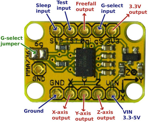
GND: Connect to ground (0V) on your microcontroller.
VIN: Connect to 5V on your microcontroller. The accelerometer module itself runs at 3.3V, but it includes an onboard voltage regulator that converts the power provided on VIN to 3.3V.
X: Analog output for the X-axis reading. Connect to an analog input on your microcontroller.
Y: Analog output for the Y-axis reading. Connect to an analog input on your microcontroller.
Z: Analog output for the Z-axis reading. Connect to an analog input on your microcontroller.
SLP: "Sleep" input, active LOW. Pull this to GND to put the accelerometer to sleep. The module includes a pull-up resistor on this input, so you can leave it unconnected in normal use.
TST: "Test" input, active HIGH. Pull this high to put the accelerometer into a self-test mode. Leave unconnected in normal use.
0g: Freefall (0g) detection output. This output is driven HIGH when the accelerometer module detects that it's in freefall, so you can connect it to an interrupt input on your microcontroller to have your project react immediately if it's dropped.
gS: G-select input. Pulling this input HIGH puts it into 6g mode. By default the module is in 1.5g mode.
3V3: Output from the onboard 3.3V voltage regulator.
6g: Solder jumper to force the module into 6g mode.
Basic Connections

In this example we've connected the X axis to A0, the Y axis to A1, and the Z axis to A2. GND on the module connects to GND on the microcontroller, and VIN on the module connects to 5V on the microcontroller.
Reading Values
The X, Y, and Z axis outputs vary proportionally with acceleration. With the connections shown above you can read the current values five times per second and display them using the serial console using the sketch shown below. Open the Arduino IDE, create a new sketch, and paste in the following code:
int xAxis = A0;
int yAxis = A1;
int zAxis = A2;
int axisValue = 0;

void setup() {
  Serial.begin(38400);
  Serial.println("Starting up");
}

void loop() {
  axisValue = analogRead(xAxis);
  Serial.print("X=");
  Serial.print(axisValue);

  axisValue = analogRead(yAxis);
  Serial.print(",Y=");
  Serial.print(axisValue);

  axisValue = analogRead(zAxis);
  Serial.print(",Z=");
  Serial.println(axisValue);

  delay(200);
}
Upload the sketch to your microcontroller, open the serial console, make sure it's set to 38400bps to match the setting in the sketch, and try moving the AM3X around to see the values change.
Understanding The Output Values
The outputs have a voltage proportional to the acceleration currently being experienced. Because each axis can display both positive and negative values, the outputs are offset to half the operational voltage of the accelerometer chip. The chip runs at 3.3V, so any axis that is experiencing 0 acceleration should read approximately 1.65V.
A scaling factor is then applied depending on whether the module is in 1.5g or 6g mode. In 1.5g mode (the default) the outputs vary by 800mV/g, which means that an output experiencing +1g acceleration will show:
1.65V + (1 x 0.8V) = 2.45V
Similarly, when experiencing -1g acceleration it will show:
1.65V + (-1 x 0.8V) = 0.85V
If you have the module sitting horizontal and still, both the X and Y axes should be experiencing 0g acceleration so they will output approximately 1.65V. However, the Z (vertical) axis will be experiencing +1g due to the effect of gravity, so it will output approximately 2.45V.
Likewise, if you tilt the module vertically so that the X axis is vertical you will see 1.65V (0g) on the Y and Z axes, and 2.45V (+1g) on the X axis.
In 6g mode the operation is the same, but the outputs vary by just 206mV/g.
But what do all these voltages mean when you read them into your Arduino using analogRead?
By default, the analogRead function measures voltages between 0V and 5V (the operational voltage of the microcontroller) on a scale of 0 to 1023. Reading an axis that is at 0g (and therefore 1.65V) will return a value of approximately:
(1023 / 5) x 1.65 = 338
When sitting horizontal and still, the Z axis will output approximately 2.45V as explained above so the reading is expected to be approximately:
(1023 / 5) x 2.45 = 501
Recalibrating The Analog Inputs
A handy trick for advanced users is to change the AREF (analog reference) value on the Arduino itself to force the analog inputs to read a full-scale value of 3.3V. The default input range of 0-5V wastes the top part of the range when dealing with a 0-3.3V device such as the AM3X, so recalibrating it to treat 3.3V as full-scale will give you better resolution and make the maths easier to deal with! Instead of a 0g value being offset near the bottom of the 0-1023 range, it will be right in the middle at 511.
To change the input range on the analog inputs, use a short jumper wire to connect the AREF pin to the 3.3V pin on the Arduino. Then add the following line to the setup() routine in your sketch:
analogReference(EXTERNAL);


