


Note: Pictures below are for KitTen v1.0. Later versions have been updated to the "R3" header format, which replaces one of the 8-way headers with a 10-way header. The assembly steps are otherwise the same.
The KitTen has been designed for easy assembly and you may find you can assemble it simply by following the overlay printed on the PCB. Even if you have no previous experience with electronics you should be able to get through it by following this guide.
Note that this guide does not attempt to teach you how to solder: if you've never soldered before, please see www.freetronics.com/how-to-solder.
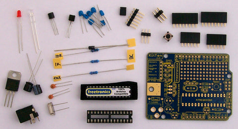
Step 1: Check / Identify Required Parts
You'll find that some of the parts in the KitTen look very similar but they are actually quite different, and it's important that you insert the parts in the correct locations. At each step we'll explain how to tell which part is which, but for now spread them out on a tray or clear bench area so you can see them clearly.
| Qty | Part |
| 1 | 1K resistor |
| 1 | 2K2 resistor |
| 1 | 10K resistor |
| 2 | 22pF ceramic capacitor |
| 7 | 100nF ceramic capacitor |
| 2 | 47uF 25V electrolytic capacitor |
| 1 | 1N4001 power diode |
| 1 | 16MHz crystal |
| 1 | 2N7000 MOSFET |
| 1 | 78LS33 3.3V voltage regulator, TO-92 package |
| 1 | 7805 5V voltage regulator, TO-200 package |
| 1 | Red 3mm LED |
| 1 | Blue 3mm LED |
| 1 | Atmel ATmega328P MCU |
| 1 | 28-pin DIP IC socket |
| 1 | 2.1mm PCB-mount DC jack |
| 1 | PCB-mount tactile button |
| 1 | 1x6 male header, 90 degree bend |
| 1 | 1x3 male header |
| 1 | 2x3 male header |
| 2 | 1x6 female header |
| 2 | 1x8 female header |
| 1 | 2-way female header jumper |
| 1 | KitTen PCB |
Step 2: Resistors
A good general principle is to fit the lowest parts first. The lowest parts on the board are the three resistors, and we've provided special small-bodied resistors to keep everything neat. Generally the only way to tell them apart is to either read the colour codes (very difficult on modern resistors!) or measure them with a multimeter, so we've written the value of each resistor on the tape on one of the legs. Pull off the tape and fit the resistors one at a time so you don't mix them up.

As you insert each resistor, bend the leads out at 45 degree angles underneath the PCB. This holds it in place while you turn it over to solder each lead.

After the leads are soldered, trim off the excess length with side cutters.
Step 3: 5V Voltage Regulator, Diode, and Reset Button
Fitting the 5V voltage regulator is a little tricky, so it's best to do it early on before other parts get in the way. Start by using a pair of pliers to bend the leads 90 degrees as shown in the photo.
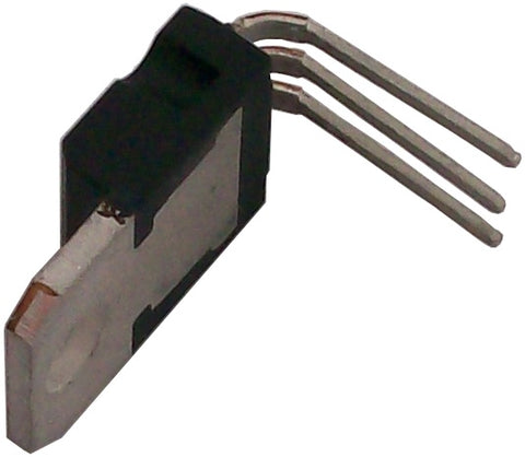
The leads have to pass down through the PCB while the regulator lies flat on the board.

Solder the leads under the PCB and trim them off. Now for the tricky bit: soldering the regulator heatsink to the PCB. Directly under the regulator body is a bare metal surface on the PCB, and by thermally connecting the regulator to the PCB we can use the PCB itself to help dissipate heat generated by the regulator. One common way to do that is to use a small nut and bolt through the hole to clamp the regulator to the PCB, but we'll solder it instead.
The corners of the heatsink have small chamfers cut off them, exposing a small part of the PCB surface underneath. Push your soldering iron into the chamfer to heat up both the heatsink and the PCB surface at the same time so that you can get solder to bond to them both and join them together. Because the heatsink and the exposed PCB surface have a lot more thermal mass than a typical component lead you'll need to apply a good amount of heat before solder will melt and adhere to them.
When that's done, clip the tactile button into place and solder it under the PCB. The leads are spaced so that it can only be clipped into place with the correct orientation, so don't force it by bending them out of shape. If you have to do that, it's possible you have it oriented the wrong way around.
Next bend the leads of the power diode 90 degrees so that you can slide it into position on the PCB. Diodes are polarised, so you have to be very careful that you insert it the correct way around. One end of the diode is marked with a band printed around the body, and you'll see on the PCB that one end is similarly marked. Make sure the marks match each other and you'll be fine.
Step 4: Ceramic Capacitors and Crystal
There are two types of ceramic capacitor in the kit: a pair of 22pF capacitors used with the crystal to provide the 16MHz clock for the MCU, and seven 100nF capacitors that provide various functions (mainly power supply decoupling) around the circuit.
The 22pF capacitors will be an orange-tan colour, and have "22" printed on them. They go in right next to the location for the crystal. Ceramic capacitors aren't polarised, so it doesn't matter which way around you fit them. It's customary however to have the markings consistently aligned to make it easier to read them.
The 100nF capacitors will be either blue or a light tan colour, and have "104" printed on them. Find all the spots on the PCB marked "100n" and fit them in place.

Finally, insert the crystal as shown in the photo and solder it in place. Try not to use excessive heat on the crystal: you've had a bit of practice by this point so you should be quite smooth and fast by now! It's not polarised, so fit it either way around.
Step 5: IC Socket, Electrolytic Capacitors, and LEDs
All the parts in this step are polarised, so make sure you install them the right way around! Don't worry, it's easy to tell which way they go.
The electrolytic capacitors have black cylindrical bodies and one lead longer than the other: the longer lead is positive, and the shorter lead is negative. They're also marked on the body to show the negative lead so you can tell which is which even if they've been cut.
If you look at the PCB you'll see that there is a little "+" symbol printed next to the positive lead of each electrolytic capacitor. Insert them into the PCB, bend the leads out 45 degrees as usual, solder, and trim them off.

The 28-pin IC socket itself isn't technically polarised, but it's important to get it around the right way because it includes a little indicator notch that shows how the IC should be plugged in. You'll see one end of the socket has a small notch in it to indicate the location of pin 1. The PCB overlay also shows the ends of the socket, with one end straight and one end notched. Match the notches together, insert the socket, and solder it in place. It may tend to want to fall out while you're trying to solder it, so you may find it handy to use a bit of tape or Blu-tack to hold it down until you've soldered at least a few pins on.
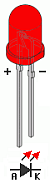
There are two LEDs to install, one red and one blue. The red LED will be obvious because the case is tinted, but blue LEDs generally have clear cases so you can't tell what colour they are until you power them up.
Just like electrolytic capacitors, LEDs have different length legs: long for positive (anode), short for negative (cathode). Once again there is a tiny "+" symbol on the PCB next to the positive hole, which is the top hole for both LEDs. The LED body also has a flat spot next to the negative lead so you can figure out the orientation if the leads have been cut.
Step 6: Male Headers
There are three different types of "male" break-away headers supplied in the kit. The 1x6 header with the 90 degree bend mounts on the top left of the PCB, and the 1x3 header mounts just behind it. The 2x3 header mounts at the other end of the board as the ICSP header.

Soldering headers on is a great way to burn your fingers because the heat travels straight up through them, so you may want to resort to tape or Blu-tack again to hold them while soldering.
Step 7: 2N7000 MOSFET and 78l33 3.3V Voltage Regulator
Unfortunately the 2N7000 MOSFET and the 78l33 3.3V voltage regulator look extremely similar, and you may have some trouble telling them apart. They are both in a TO-92 package with three leads, and the only difference is the part number printed on the front face. The print is likely to be very small though, so you may need a good light and perhaps a magnifier to be able to make out any of the markings.
The MOSFET, which is marked "2N7000", is fitted near the bottom right of the PCB next to the IC socket. You'll probably have to bend the middle lead out slightly to make it fit into the holes on the PCB, and you don't need to push it right down flush. Doing so would put mechanical strain on the leads so TO-92 packages are typically mounted so that they float a few millimeters above the surface of the PCB.
The 3.3V voltage regulator, which is marked "78l33" or similar, goes near the electrolytic capacitors. Follow the same procedure as with the MOSFET to mount it a little proud of the PCB.
Step 8: Female Headers, Power Jack, MCU, and Power Selector
You're almost done!
By this point you'll be an expert, but be careful: fitting the pairs of 1x6 and 1x8 female headers into position on the edges of the PCB is not quite as simple as you may think. It's surprisingly hard to get them straight, and if you don't get them in the right spot it can be hard to fit a shield on top.
The trick to soldering the female headers is to use a shield as a jig to hold them in place. If you have a shield, plug the loose headers onto the shield pins and then fit them onto the KitTen PCB. The shield will hold them straight while you solder them on. Then you just remove the shield and you'll have perfectly aligned headers on your KitTen.

The 2.1mm DC jack goes into position on the bottom left of the PCB, and then you're ready to insert the MCU. We've left it stuck into a block of anti-static foam, so try not to handle the pins too much once you remove it from the foam.
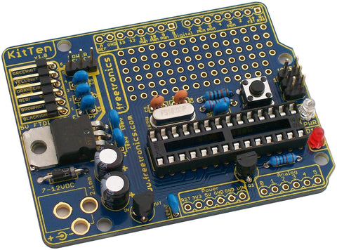
The MCU must be installed the right way around, and if you look carefully at the ends of the body you'll see that one of them has a small notch in the plastic. Once again that's the end near pin 1, and it has to align with the notch in the IC socket. If you have your KitTen oriented like in the photo above, the notch needs to be on the right. If we've done our job properly the MCU sticker should end up the right way around as shown, but don't just trust the sticker: always look at the body of the MCU to check that you know which end is which.
When you try to insert the MCU into the socket you'll probably find (frustratingly!) that the MCU pins spread out slightly and won't fit in. To make the pins fit you can put the MCU down sideways on your workbench and push down on it firmly while holding the ends, bending the legs in until they're a bit straighter. Do it evenly on both sides and you should be able to push the MCU down into the socket until it seats properly.
Finally, do a quick visual inspection of the MCU to make sure that no stray pins ended up bent out sideways and missed the IC socket. If there are, use a small screwdriver or similar to lever the chip out of the socket evenly from the ends, bend the pins into place, and try again.
Once you're happy with that, do a broader visual inspection of the whole board. Look for solder bridges between pins, bits of cut-off component leads, or anything else that seems out of the ordinary.
Plug the power source selector across the two leftmost pins of the 3-way male header to select USB as the power source, and you're ready to try it out.
Step 9: Power Up
The big moment. Using a 5V USB-to-serial adapter or similar with FTDI-type connections, plug it into the header in the top left as shown. The lead colours are printed on the PCB, but the important thing to remember is that green goes at the top. Other colours may vary depending on the manufacturer of the adapter.

Plug the other end of the cable into your computer, start the Arduino IDE as usual, and select the correct serial port. Set the board type to "Arduino Duemilanove or Nano w/ ATmega328", and have fun playing with your new KitTen!


